
CODE UPDATE

Update #18 Main Disconnect Grounding
Let's define a few terms first:
(Most of the definitions and all of the citations in this update are found in the NEC - 2005 (NFPA 70))
Bonding (Bonded): The permanent joining of metallic parts to form an electrically conductive path that ensures electrical continuity and the capacity to conduct safely any current likely to be imposed. (NEC)
Effective Ground-Fault Current Path: An intentionally constructed, permanent, low-impedance electrically conductive path designed and intended to carry current under ground-fault conditions from the point of a ground fault on a wiring system to the electrical supply source and that facilitates the operation of the overcurrent protective device or ground fault detectors on high-impedance grounded systems. (NEC)
Effectively Grounded: Intentionally connected to earth through a ground connection or connections of sufficiently low impedance and having sufficient current-carrying capacity to prevent the buildup of voltages that may result in undue hazards to connected equipment or to persons. (NEC)
Ground: A conducting connection, whether intentional or accidental, between an electrical circuit or equipment and the earth or to some conducting body that serves in place of the earth. (NEC)
Ground: A large conducting body, such as the earth or an electric circuit connected to the earth, used as an arbitrary zero of potential. (American Heritage Dictionary)
Grounded: Connected to earth or to some conducting body that serves in place of the earth. (NEC)
Ground Fault: An unintentional, electrically conducting connection between an ungrounded conductor of an electrical circuit and the normally non-current-carrying conductors, metallic enclosures, metallic raceways, metallic equipment, or earth. (NEC)
Ground-Fault Current Path: An electrically conductive path from the point of a ground fault on a wiring system through normally non-current-carrying conductors, equipment, or the earth to the electrical supply source. (NEC)
Conductors
Grounded Conductor: A system or circuit conductor that is intentionally grounded. (Identified by a continuous white or gray outer finish or by three continuous white stripes on other than green insulation along its entire length. "The Neutral Wire" "White Wire" (See 310.12))
Equipment Grounding Conductor: The conductor used to connect the non-current-carrying metal parts of equipment, raceways, and other enclosures to the system grounded conductor, the grounding electrode conductor, or both, at the service equipment or at the source of a separately derived system. (Shall be permitted to be bare, covered, or insulated. Individually covered or insulated equipment grounding conductors shall have a continuous outer finish that is either green or green with one or more yellow stripes. "The Ground Wire" "Green Wire" (See 310.12))
Ungrounded Conductor: Conductors that are intended for use as ungrounded conductors, whether used as a single conductor or in multiconductor cables, shall be finished to be clearly distinguishable from grounded and grounding conductors. ("The Hot Wire" "Black Wire" (See 310.12) - I could not find a formal definition for ungrounded conductor in the NEC...but we do know it normally carries current and in most applications is not intentionally grounded.)
![]()
Did you fall asleep yet?!
Grounding is not really down to earth in it's simplicity is it? (A little humour for our British/Australian friends.)
Now I'm not going to pretend to be an "expert" on grounding, however, I would like to address a few problems that seem to come up on a regular basis.
Grounding is a really big deal in the electrical trade. It should be in our trade as well. Some of the mistakes or omissions that are made when attempting to provide an effective ground-fault current path can cause injury, loss of life, or property damage. Please note that almost all conductor nomenclature in the electrical code is in reference to ground (ungrounded conductor, grounded conductor, equipment grounding conductor, etc.).
I'd like to zero in on just few of the "grounding/bonding" issues I have encountered in the past that I feel are easy to correct.
Several times when inspecting private residence elevators and platform (wheelchair) lifts that are supplied with 240 or 120 VAC single phase power, I noticed that the grounded conductor was connected to the equipment grounding conductor at the main line disconnect. This is not allowed. (See 250.24(A)(5) - Of course there are exceptions to almost all of the NEC requirements but the few narrow and specific exceptions allowed by this requirement do not concern us in the vertical transportation trade.) The particular disconnect I am recalling was wired on the line side using a three-conductor with ground nonmetallic-sheathed cable (Type NMC - See Article 334). This particular controller required 240 VAC single phase power so the grounded conductor was not required to be carried over to the controller. Someone decided to connect the grounded conductor to the grounding bus along with the equipment grounding conductors. The "Heads Up" below will explain why you should not do this - with the aid of a slightly different but easier to understand circuit.
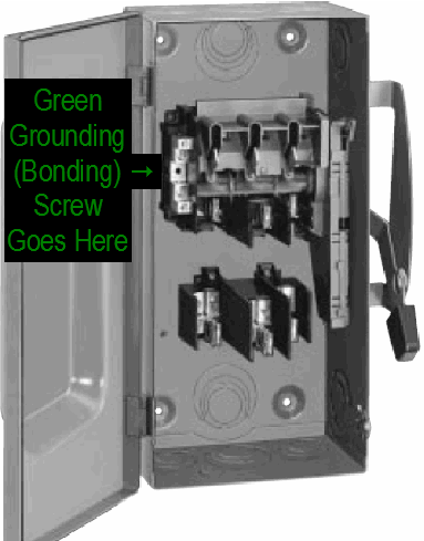
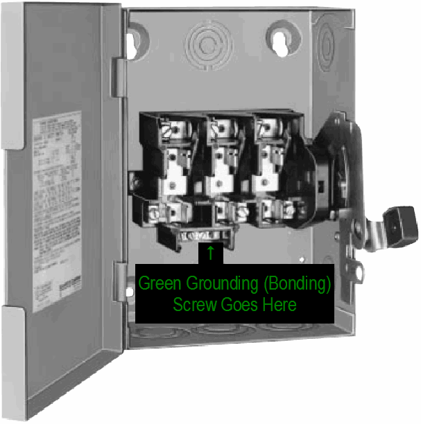
Figures #1 and #2 represent two typical disconnects used in the vertical transportation industry. (I "borrowed" these images from this Square D Enclosed Safety Switches PDF document.) The correct location for the grounding (bonding) screw is indicated. I have found many disconnects that are missing this bonding screw. If the electrician is running a separate equipment grounding conductor and it is connected to this bus it should be used as intended. The disconnect is not properly grounded when the bonding screw is missing. Without the bonding screw the neutral bus, which is now the grounding bus, is above ground. See Figure #3 and Figure #4 for a close-up of these connections.

Figure #1
Square D General Duty Safety Switch - Class 3130

Figure #2
Square D General Duty Safety Switch - Class 3130
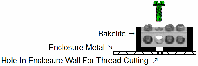
Figure #3 is a close-up of a typical grounding bus arrangement with respect to the relationship between the various parts. The grounding (bonding) screw is designed to pass through the bakelite and securely bond the grounding bus to the enclosure wall. If the correct length screw is provided, and installed, the bus will be securely bonded. If a screw that is longer than required is installed and the enclosure is mounted on a concrete wall the screw may seem tight but the bus will not be securely bonded because the screw has "bottomed-out" against the concrete.

Figure #3
Square D General Duty Safety Switch - Grounding Bus
Things To Do
1 - Insure that the main disconnecting means is properly grounded and bonded. (See 250.4)
2 - Use the listed grounding screw or device provided in the disconnect, enclosure, or box for grounding. (See 250.8 and 250.148(C))
As you can see from the image below (Figure 4), also "borrowed" from this Square D Enclosed Safety Switches PDF document, the neutral can be grounded with the addition of a bonding screw. Also, if a neutral bus is required then a grounding kit can be purchased and installed in the field. Generally speaking, this would only be required when the disconnect is used as service equipment and marked, "Suitable for Use as Service Equipment". In this case the grounded conductor and the equipment grounding conductor are connected together. We are not installing service equipment. (See "switches, enclosed" in the UL Whitebook - General Information for Electrical Equipment Directory 2005)

Figure #4
Square D Insulated Groundable Neutral & Grounding Kit
3 - It is not mandatory for the grounding (bonding) screw to be green in color, however, use the listed screw that was provided by the manufacturer for their listed device. The code only requires the screw (bonding jumper) to be green if it is the main bonding jumper or the system bonding jumper. We are not working with either one of these bonding jumpers. (See 250.28 - Be sure to read the definitions for "bonding jumper, main" and "bonding jumper, system" in the NEC definition section.)
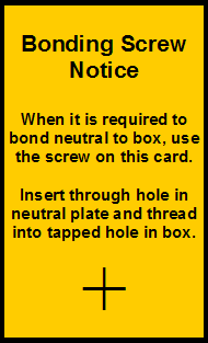
I found the following card (Figure #5) with a green bonding screw pushed through the crosshairs in a main line disconnect switch enclosure. I have also found the green bonding screw secured in place in one of the terminals of the neutral bus as if it were a conductor. This is the screw to use. If it is missing ask the electrician for one.

Figure #5
Bonding Screw Notice
Things Not To Do
1 - Never connect the grounded conductor to ground or to the equipment grounding conductor. (See 250.24(A)(5))
2 - Never use a sheet metal screw to "land" an equipment grounding conductor. This includes "Tek" screws, drywall screws, or any screw with a coarse thread. (See 250.8)
3 - Never drill a hole in an enclosure to "land" an equipment grounding conductor with a bolt or screw. The enclosure will be provided with a grounding screw hole or other listed grounding device. The listing approval of the enclosure may be invalidated by this action. (See 250.8 and 250.148(C))
4 - Never use a 1/4-20 bolt and nut with a flat washer as a grounding terminal - it is not a listed device. "Grounding conductors and bonding jumpers shall be connected by exothermic welding, listed pressure connectors, listed clamps, or other listed means." (See 250.8)
5 - "The structural metal frame of a building shall not be used as the required equipment grounding conductor for ac equipment." (See 250.136(A))
6 - Rule 620.53 requires "a single means for disconnecting all ungrounded car light, receptacle(s), and ventilation power-supply conductors for that elevator car." This device "shall be a fused motor circuit switch or circuit breaker" and "shall be located in the machine room." Rule 240.22 states, "No overcurrent device shall be connected in series with any conductor that is intentionally grounded ("white conductor" or "neutral conductor") unless..." One of the exceptions is if the "overcurrent device opens all conductors of the circuit..." If you are using a fused disconnect as this "single means" then the "white wire" should not be fused. If for some reason this fuse opens the "black wire" will still be hot because its fuse may not open. I would recommend running the "white wire" through the disconnect without connecting it to a contact.
So you see there are many things to consider when grounding a circuit, system, enclosure, or device.
![]()
![]()
![]()
 E-mail Bob Desnoyers with your main disconnect grounding comments
Welcome/Contact ![]() Résumé
Résumé ![]() Elevator Utilities
Elevator Utilities ![]() Hydraulic Utilities
Hydraulic Utilities
Electric Utilities ![]() Odds & Ends
Odds & Ends ![]() Code Updates
Code Updates ![]() Testimonials
Testimonials
