
CODE UPDATE

Update #13 Contactors & Relays for Use
in Critical Operating Circuits (2.26.3)
2.26.3 - "Where electromechanical contactors or relays are provided to fulfill the requirements of 2.26.8.2, and 2.26.9.3 through 2.26.9.7, they shall be considered to be used in critical operating circuits. If contact(s) on these electromechanical contactors or relays are used for monitoring purposes, they shall be prevented from changing state if the contact(s) utilized in a critical operating circuit fail to open in the intended manner. The ability of the monitoring contact(s) to perform this function shall not be solely dependent upon springs."
A critical operating circuit is defined by 2.26.3 as those circuits, operations, and devices mentioned in 2.26.8.2 and 2.26.9.3 through 2.26.9.7, which use relays, switches, or contactors for monitoring purposes. The monitoring determines whether a critical contact has remained in the "On" or "Closed" position when it should be "Off" or "Open."
Some of these safety circuits and devices are:
A failure in the brake circuit (2.26.8.2)
A failure that would render any electrical protective devices to be ineffective (2.26.9.3(a))
A failure that would allow the car to move out of the leveling zone with a car or hall door open (2.26.9.3(b))
A failure permitting excessive speeds during access, inspection, or leveling operation (2.26.9.3(c))
A failure which would permit normal operation when on access, inspection, or bypass operation (2.26.9.3(d))
A failure that would continue to make ineffective any door or gate interlock or contact when either a bypass or access switch is in the "OFF" position (2.26.9.3(e))
A failure in the devices controlling elevators with driving motors employing static control without motor generator sets (usually DC motors) (2.26.9.5)
A failure in the devices controlling elevators employing alternating current driving motors driven from a direct current power source through a static inverter (always AC motors) (2.26.9.6)
A failure in the "suicide circuit" of an elevator employing generator field control (always DC motors) (2.26.9.7)
Relays, switches, and contactors in these circuits must monitor their own status. You may have noticed that many of the critical relays, switches, and contactors on electric elevators conforming to the A17.1 - 2000 code and later editions drop-out after each run. (Even the safety chain relay which is traditionally always "Up" on vintage elevators drops-out after each run of the car.) A circuit similar to the following example will be found somewhere in the wiring diagram. If the processor does not receive the signal (ACO) that all the devices have dropped-out the car can not run again.

Circuit to Check That All Contactors Are Open
The types of relays, switches, and contactors used in these critical circuits have several names. They might be called force-guided, positively guided, captive contact, or safety relays. The main difference between these relays and "regular" relays is that the normally open and normally closed contacts must be mechanically linked so that both can not be closed at the same time. The following image depicts two sets of contacts arranged in a force-guided configuration.

Properly Operating Force-Guided Relay With No Defects
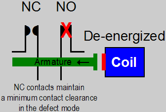
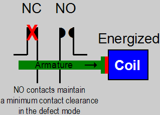
Without a relay failure the contacts operate as expected, however, when there is a contact failure the relay would operate in the following manner.

Properly Operating Force-Guided Relay With A NO Contact Defect

Properly Operating Force-Guided Relay With A NC Contact Defect
Most of us have seen relays that will continue to operate with a set of contacts "welded" together. If any of the contacts in a force-guided relay "weld", and the elevator control circuitry is designed to monitor this malfunction, the controller will be alerted to the malfunction and provide an appropriate response. Typically, the response is to prevent the car from running again until the fault has been cleared. If we can consistently predict the performance of control hardware under fault conditions we can reliably design safety circuits for elevator service.
Allen-Bradley provides the following definition of positively guided:
"The term "positively guided" is generally used in reference to auxiliary contacts in safety circuits which are used to monitor normally open contacts within relays or contactors used in such installations. A summary of the requirements dictate that if the power contacts weld, the auxiliary contacts shall not change state upon de-energizing the contactor. The concept of "mirror contacts" is used to describe this type of performance. Positively guided auxiliaries provide a form of self-monitoring in the relay should any of the power contacts weld."
Omron provides the following definition of force guidance:
"Force guidance in a relay means that the contacts in a contact set must be mechanically linked together so that it is impossible for the NO (Normally Open) making contacts and the NC (Normally Closed) breaking contacts to be closed at the same time. There must be a 0.5 mm (0.019685 in.) minimum air gap between open contacts for the entire service life of the relay, even in the case of a failure. The force guidance of the relay contacts must always be preserved even in the event of any malfunction."
"It is also interesting to note that under the provisions of ANSI B11.1-1990 Sec. 5.5.1, that redundant safety systems (for example, a control reliable system) that require the usage of relays must use relays that have a positive relationship between the Normally Open (NO) contacts and the Normally Closed (NC) contacts. Omron calls this feature force-guided safety contacts. The way force-guided safety relays work is that if at least one normally open contact becomes welded, when the coil is de-energized, all normally closed contacts maintain a gap of at least 0.5 mm (0.019685 in.) or greater. Even if a normally closed contact is welded, all normally open contacts maintain a gap of at least 0.5 mm (0.019685 in.) in the coil-energized mode."
Here is a very interesting article by Pat Fleming of Motion Control Engineering on this topic with respect to elevator controllers.
![]()
![]()
![]()
 E-mail Bob Desnoyers with your critical operating circuit relay comments
Welcome/Contact ![]() Résumé
Résumé ![]() Elevator Utilities
Elevator Utilities ![]() Hydraulic Utilities
Hydraulic Utilities
Electric Utilities ![]() Odds & Ends
Odds & Ends ![]() Code Updates
Code Updates ![]() Testimonials
Testimonials
