
CODE UPDATE

Update #11 Terminal Stopping Devices
Hydraulic Elevators (3.25)
Occasionally I have trouble convincing an installer that he does not have the correct terminal stopping devices installed on his hydraulic elevator for the top terminal landing. (These discussions usually involve elevator contractors installing "homebuilt" controllers.) The code requires a normal terminal stopping device (NTSD) at the top and bottom terminal landings and if the car speed exceeds 50 FPM a terminal speed reducing device (TSRD) must be installed for the up direction. (See 3.25.1 & 3.25.2) Stopping switches located on the car or in the hoistway and which are operated by cams located in the hoistway or on the car are to be designed in accordance with 2.25.1. (See 3.25.1.3) Essentially, the switches may be mechanically operated, magnetically operated, optical, or solid-state devices. On hydraulic elevators I often see mechanical switches operated by cams. Sometimes the switches are mounted on the car. Often they are installed on the rail and operated by cams attached to the car - I have "designed" the images in this update to this configuration. The "prints" I have provided as examples are very rudimentary and for clarity I have omitted much of the circuitry found on a typical hydraulic elevator. These are just examples - you will never see prints like these - and that's OK. We have to get accustomed to reading all sorts of different styles of wiring diagrams. This is just one more style.
When I'm inspecting a hydraulic elevator with a rated speed over 50 FPM and I see only two switches when I step onto the car top I start asking questions. The conversation usually goes something like this:
Me: "Where's your normal terminal stopping device?"
Technician: "That's the top switch. It stops you at the floor."
Me: "Where's your terminal speed reducing switch?"
Technician: "That's the bottom switch. It slows you down."
Now the hard part begins. I have to try to convince him that the top NTSD must "slow down and stop the car automatically at or near the top landing." (See 3.25.1.1) This usually requires two switches:
The TSRD requires a third switch. (See 3.25.2.2.1.) This means the same switch can not be used for both the NTSD and the TSRD. It also means you can not wire the two switches in series and have them control the same means for reducing the speed. (See 3.25.2.2.4) You wouldn't want the same switch performing two different functions because if the switch malfunctioned for any reason (roller or switch arm fell off - relay armature "stuck in") both devices would be adversely affected. Two switches in series could be "jumped-out" with a single clip jumper or wiring error. The placement of the switches in the wiring diagram is critical as well. (See 3.25.2.2.3) If any of the switch contacts go to ground in Example #1 or #2 fuse F3 will open and stop the car. If the contacts were located on the ground side of the coils, fuse F3 would not open and the switch contacts could be bypassed by a single accidental ground. (See Heads-Up... below)
I have provided 2 different examples to demonstrate how the NTSD and the TSRD can be wired and installed. There are many other ways to accomplish these stopping requirements.
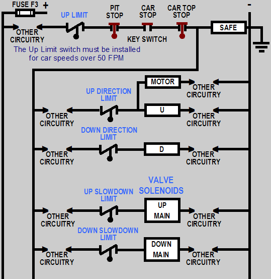
As you can see in Example #1, the Up Limit switch is being used as the TSRD. When this switch opens its contacts, the feed to all the other relays, contactors, and solenoids is interrupted. The car speed is reduced "to ensure that the plunger does not strike its solid limit of travel (stop ring) at a speed in excess of 0.25 m/s (50 ft/min)." (See 3.25.2.1) When this switch opens the car speed is quickly reduced to 0 FPM. If this arrangement is employed you must check the exact position of the car when the Up Limit contacts actually open. The Up Limit switch contacts must open early enough to allow the car to stop without striking the plunger stop ring at a speed in excees of 50 FPM. The gravity stopping distance for a 125 FPM car is approximately 0.800" and I'm not sure just how quickly the pump motor stops and the up valve solenoid closes. By the way, the Up Limit switch is operating exactly as a final terminal stopping device (final limit) would operate - preventing car motion in either direction of travel - but a final terminal stopping device is not required on a hydraulic elevator. (See 3.25.3)
Merely depressing the Up Limit switch roller arm with your hand when on car top inspection to see if it stops the car in both directions of travel does not sufficently test this device. You have to know the car position when the cam actually opens the contacts. You can do this when you check the top runby of the car (See 3.4.2.2) and the pressure at which the relief valve opens. (See 3.19.4.2) An easy way to perform this test is to run the car up on access at the top floor until the Up Direction Limit switch contacts open. Record the sill to sill measurement. Have the technician jump these contacts. Run the car up until the Up Limit switch contacts open. Record the sill to sill measurement. Have the technician jump these contacts. Run the car up onto the stop ring. Record the sill to sill measurement and the pressure at which the relief valve opens. The inspectors manual requires that we stress the entire hydraulic system at the relief valve pressure setting by inching the car up onto the stop ring. After this procedure the cylinder test (static test) would be performed on inground jacks and underground pressure piping to determine if any leaks exist.
The Up Slowdown Limit contacts control the high speed portion of the control valve. The Up Direction Limit contacts control the slow speed portion of the control valve (indirectly through the U relay - the up leveling solenoid is not shown) as well as the pump motor contactor. When these contacts open the car should slow down and stop at or near the top terminal landing.

Example #1 Wiring Diagram
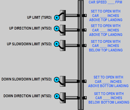
The switch tree shown below illustrates the position of the switches as mounted on the rail. The person preparing the wiring diagram will fill in the correct car speed and the appropriate switch placement dimensions with respect to the car and landing sills.

Example #1 Switch Tree
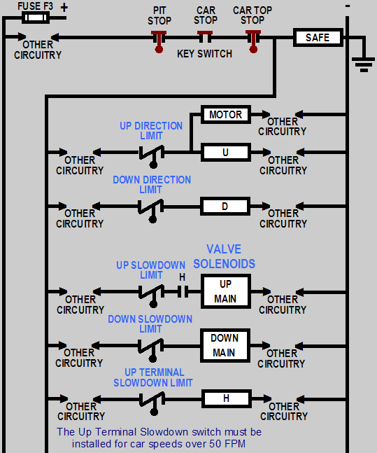
Example #2 depicts a slightly different arrangement for the TSRD. The Up Terminal Slowdown Limit contacts control the H relay (high speed). A contact on the H relay controls the high speed portion of the control valve. The Up Slowdown Limit and the Up Direction Limit work essentially in the same manner as Example #1.

Example #2 Wiring Diagram
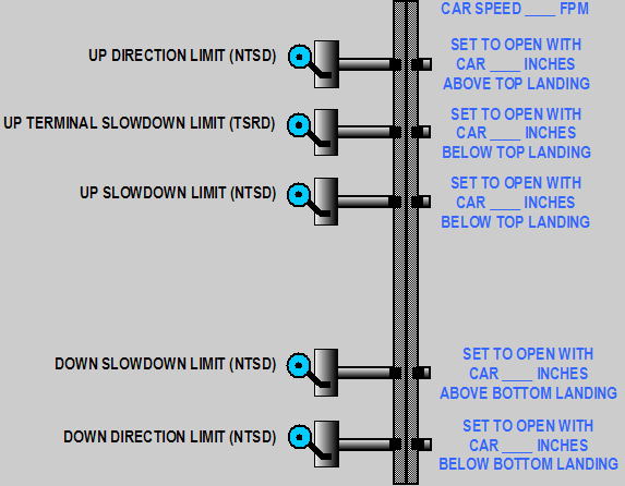
The switch tree shown below illustrates the position of the switches as mounted on the rail. The person preparing the wiring diagram will fill in the correct car speed and the appropriate switch placement dimensions with respect to the car and landing sills.

Example #2 Switch Tree
A few more thoughts concerning terminal stopping devices:
![]()
![]()
![]()
 E-mail Bob Desnoyers with your hydraulic elevator terminal stopping devices comments
Welcome/Contact ![]() Résumé
Résumé ![]() Elevator Utilities
Elevator Utilities ![]() Hydraulic Utilities
Hydraulic Utilities
Electric Utilities ![]() Odds & Ends
Odds & Ends ![]() Code Updates
Code Updates ![]() Testimonials
Testimonials
